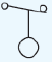
Float Switch Symbol
Functions Of Motor Control Switch Symbols Electric Equipment
Float Level Switch Principle Operation Instrumentationtools

Pump Float Switch Wiring Diagram With Schematic On Level B2networkco For Dual Septic Tank 6 9 Well Pump Pressure Switch Submersible Pump Well Pump
Www Eaton Com Content Dam Eaton Products Electrical Circuit Protection Medium Voltage Vacuum Circuit Breakers Comparison Nema Iec Schematic Diagrams Mzen Pdf
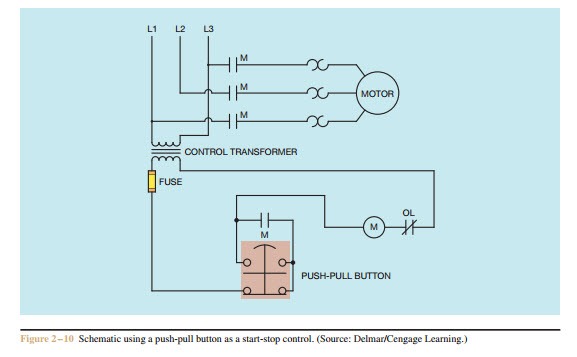
Elementary Diagrams

Level Switches Discrete Process Measurement Automation Textbook
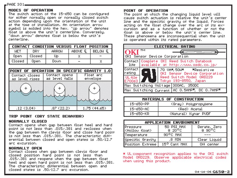
1 Pitch conduit away from the level switch when possible so that condensation will drip away from the level switch assembly Figure 2 2 When a vertical run of extension pipe is used to extend a level switch down from the top of the tank, a nonconductive silicone oil should be used to fill the vertical run Alternatively, an appropriate.
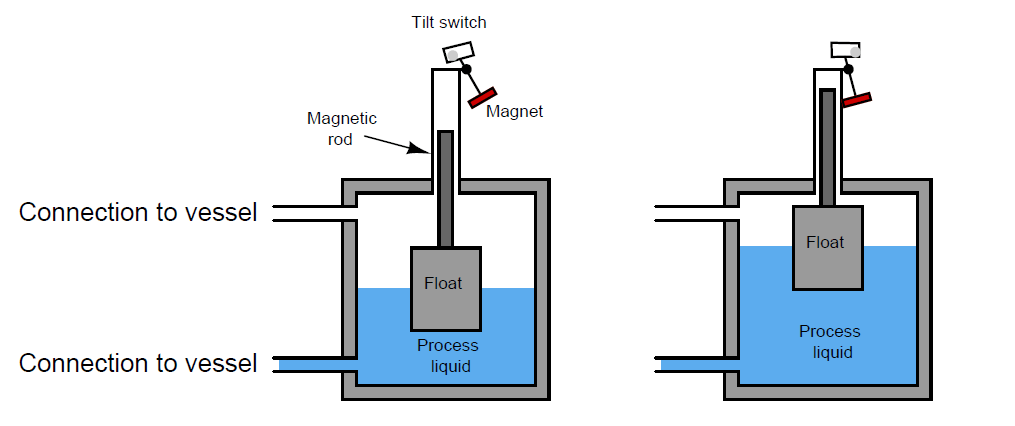
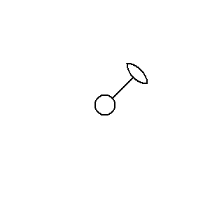
Float switch symbol. Wiring Colors & Symbols;. The is a float switch alternative that works in any water storage tank where traditional foat switches are used It can be powered by 5, 12, and 24 Volt DC CheckPoint™ is the longest lasting and lowest cost water tank level sensor on the market!. Float level switch Principle Some level switches use a float to sense the level of a liquid surface, actuating an electrical switch by the motion of the float The electrical schematic symbol for a level switch is actually based on this type of mechanism, with a round “ball” float drawn as the actuating element An example of this technology is a level switch manufactured by Magnetrol, with two such switches shown in the following photograph of a steam boiler.
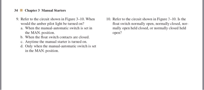
Level Switch Single Line Symbols Hydraulic Fluid Level Switch with Four NC Contacts. In addition to the various applications for float switches for vertical installation (model FLS), the model HLS horizontal float switches likewise offer innumerable possibilities to monitor and/or switch levels in order to indicate minimum/maximum levels. Flow Sensors symbols for use in electrical, pneumatic and hydraulic schematic diagrams Available in SVG, PNG, JPG, DXF & DWG formats.
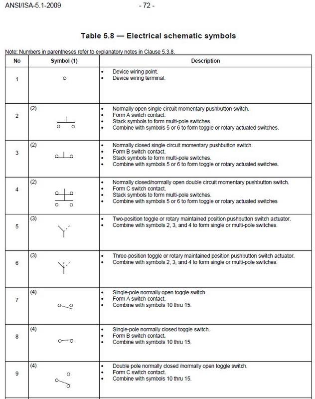
Switches Component Circuit Symbol Function of Component Push Switch (pushtomake) A push switch allows current to flow only when the button is pressed This is the switch used to operate a doorbell PushtoBreak Switch This type of push switch is normally closed (on), it is open (off) only when the button is pressed OnOff Switch (SPST). Float switch Level switch fluid Electrical & Electronic Symbols wwwelectricalsymbolscom Pushbuttons / Push Switch Symbols Go to Website 4/10 All Electrical & Electronic Symbols in https//wwwelectricalsymbolscom. Symbol of Switches, Pushbuttons, Circuit Switches The switches, pushbuttons, circuit switches are electrical, electronic or mechanical devices designed to interrupt or divert the flow of electric current or other signals in an electrical circuit.
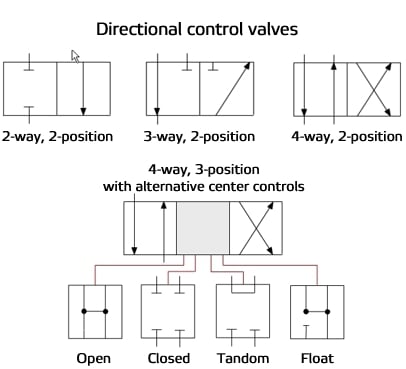
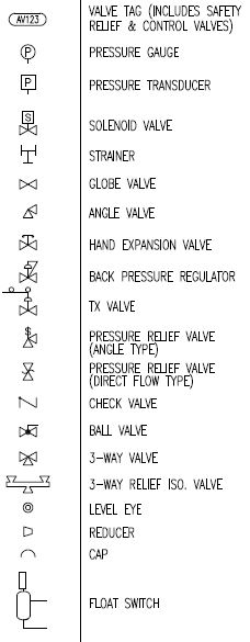
Nilight D 4 Gang Aluminum Rocker Switch Panel Toggle Dash 5 Pin ON/Off PreWired Rocker Switch Red Backlit Switch for Automotive Car Marine Boat RV,2 Years Warranty 44 out of 5 stars 42 $2159 $ 21 59 $2399 $2399. Types of symbols commonly used in drawing circuit diagrams for fluid power systems are Pictorial, Cutaway, and Graphic These symbols are fully explained in the USA Standard Drafting Manual (Ref 2) 111Pictorial symbols are very useful for showing the interconnection of components. Basic symbols for piping 2237 Spring operated safety valve 2238 Mass operated Safety valve 2228 Spring actuator 2284 Float actuator 2229 Mass 2231 Membrane actuator 2230 Piston actuator 2232 Fluid actuator 2223 Solenoid actuator 2234 Electric motor actuator 2235 Hand operated 590Angle valveBasic Symbol.
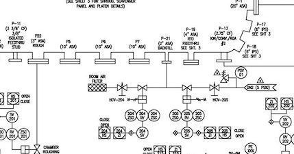
Collection of float level switch wiring diagram A wiring diagram is a simplified standard photographic representation of an electric circuit It reveals the parts of the circuit as simplified forms, as well as the power and signal links in between the tools. Float Switches for Fuels and Oils For use in locations with flammable gases and combustible dust, this switch is UL listed and CSA certified for Class I, Divisions 1 and 2, Groups C and D;. P&ID symbols exist for all major components and lines, such as valves, vessels, instruments, pumps, compressors, and towers The ISA S51, ISO , and BS 5070 cover the standardization of P&ID symbols and guide process engineers in their plant design activities The most common P&ID symbols are listed below lines.
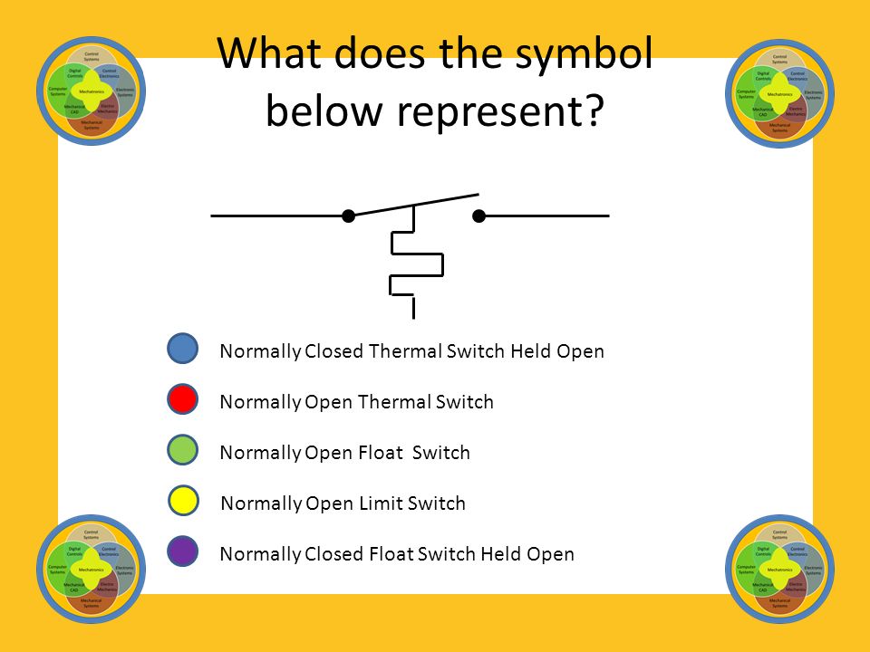
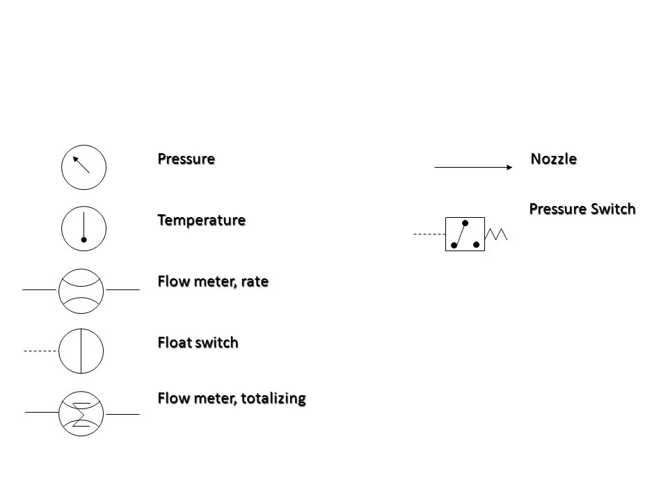
The symbol for a float switch illustrates a ball float It is drawn by adding a ____ to a line. To symbol denotes quantity one is required power, lighting panel (see lighting panel schedules) grounding, noted & lighting plans ts transf swgr mcc ldp gnd level switch pressure switch float switch limit switch selector switch cs — control switch pms — permissive sw rtd — resist temp detec thermostat. Magnetrol float level controls use a simple float and magnetic coupling action As the float rises or falls with liquid level, it moves a magnetic sleeve into or out of the field of a switch actuating magnet, causing switch operation A nonmagnetic barrier tube effectively isolates the switch mechanisms from the controlled liquid.
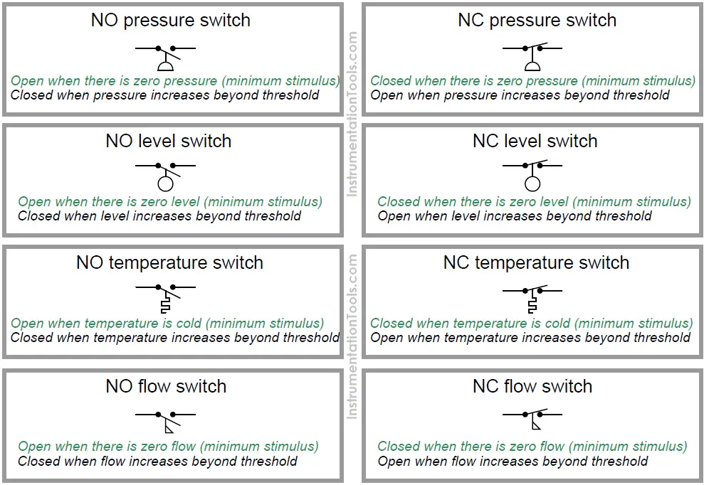
It is very important to keep in mind that the “normal” contact status of a processactuated switch refers to its status when the process is absent and/or inactive, not “normal” in the sense of process conditions as expected during routine operation For instance, a normallyclosed lowflow detection switch installed on a coolant pipe will be maintained in the actuated state (open) when. View Our Floatless Water Level Products Here. Float Switch Wiring Float Switch/level switch Installation for Water Tank by Evergreen Electrical This video is about the wiring and installation of float.
A float switch is a type of level sensor, a device used to detect the level of liquid within a tank The switch may be used to control a pump, as an indicator, an alarm, or to control other devices One type of float switch uses a mercury switch inside a hinged float Another common type is a float that raises a rod to actuate a microswitchOne pattern uses a reed switch mounted in a tube;. Float switches are highly effective at detecting pointbased limit levels for one or more switch points WIKA’s portfolio has a float switch for almost all liquid media and interfaces, regardless of foaming, conductivity, pressure, vacuum, temperature, vapors, condensation, boiling effects, turbulence, corrosion, or vibration. Horizontal float switch for side mounting to vessel Float operates air valve on outside of vessel Float mechanism is contained inside a solid metal body The air switch is located outside the metal body and is magnetically actuated Vertical float switch is mounted on top side of closed or vented vessels.
10 Unit Sequence Switch 11 – Multifunction Device 12 Overspeed Device 13 Synchronousspeed Device 14 Underspeed Device 15 Speed or FrequencyMatching Device Elect operated valve (solenoid valve) 21 Distance Relay 23 Temperature Control Device 24 – Volts per Hertz Relay 25 Synchronizing or SynchronismCheck Device. Float switches are highly effective at detecting pointbased limit levels for one or more switch points WIKA’s portfolio has a float switch for almost all liquid media and interfaces, regardless of foaming, conductivity, pressure, vacuum, temperature, vapors, condensation, boiling effects, turbulence, corrosion, or vibration. Septic Tank Float Switch Wiring Diagram – septic tank 3 float switch wiring diagram, septic tank float switch wiring diagram, Every electrical arrangement is made up of various diverse components Each part ought to be set and connected with different parts in particular manner If not, the arrangement will not work as it ought to be.
Float switch Level switch fluid Electrical & Electronic Symbols wwwelectricalsymbolscom Pushbuttons / Push Switch Symbols Go to Website 4/10 All Electrical & Electronic Symbols in https//wwwelectricalsymbolscom. The model RLS3000 float switch with temperature output combines the recording of the level and temperature of liquids in a single measuring point The stainless steel used is suitable for a multitude of media, such as, for example, oil, water, diesel and refrigerants Measuring principle. In an external chamber (bypass chamber), a float with a permanent magnet moves on a guide tube in relation to the liquid level, following the principle of communicating vessels Within the guide tube is fitted a reed contact (inert gas contact), which is energised, through the nonmagnetic walls of the float and guide tube, by the approach of.
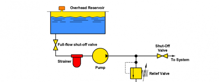
What causes load shortcircuiting and what can be done about it?. 1 Pitch conduit away from the level switch when possible so that condensation will drip away from the level switch assembly Figure 2 2 When a vertical run of extension pipe is used to extend a level switch down from the top of the tank, a nonconductive silicone oil should be used to fill the vertical run Alternatively, an appropriate. FloatOperated Valve Needle Valve 3Way Valve 2 3Way Valve 3Way Plug Valve 4way Plug Valve 4way Valve Ram Valve ElectroHydraulic Piping and Instrument Diagram Standard Symbols Detailed Documentation provides a standard set of shapes & symbols for documenting P&ID and PFD, including standard shapes of instrument, valves, pump, heating.
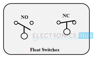
Float switch 1/18 Type ABZMS37 Component series 1X RE /17 Replaces AB 3137 Table of contents Content Page Features 1 Symbols 2 Ordering code 2. If you want to use letter suffixes, you could use LSL01A, LSH01A, LSHH01A, and LSHH01B to tag your devices In that case, I'd use the LSL for the low level switch and the LSH for the first high level switch, with both lines from each bubble feeding into a diamond with an I (for interlock) in it, and the output of the diamond feeding to the pump. Horizontal Symbol Vertical Symbol Description HSW11 VSW11 Generic Switch, Normally Open HSW12 VSW12 Generic Switch, Normally Closed HFL11 VFL11 Float/Level Switch, Normally Open HFL12 VFL12 Float/Level Switch, Normally Closed HPB11KS VPB11KS Key Switch, Normally Open HPB12KS VPB12KS Key Switch, Normally Closed HPB11KSL VPB11KSL Key Switch Latched, Normally Open HPB12KSL.
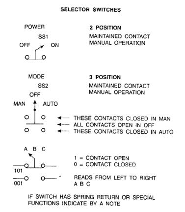
Float switch used for a sight tree in on an ammonia low pressure accumulator. Older Float Switches work by opening and closing circuits (dry contacts) as water levels rise and fall Typical float switches are normally resting in the closed position, meaning the circuit is incomplete and no electricity is passing through the wires yet Old Float Switch Working Principle. AutoOff Selector Switch AutoOffContinuous Selector Switch LeadOffLag Selector Switch LeadOffLagContinuous Selector Switch FloatOffFloat and Vacuum Continuous Selector Switch Disconnect Starter, SinglePhase with a Set of Two Overloads Starter, ThreePhase with a Set of Three Overloads Starter Coil with.
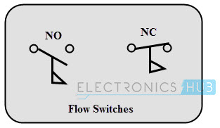
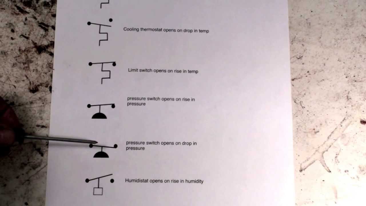
The flag symbol on the switch indicates the paddle which senses the flow or movement of liquid These switches again normally open or normally closed type configurations Pressure Switches These switches are commonly used in industrial applications in order to sense the pressure of hydraulic systems and pneumatic devices. This symbol represents a foot operated or foot pedal switch it is a single pole switch which control a circuit or motor usually used in controlling heavy machinery It has a very rugged design because it is being operated by foot. A float switch is a type of level sensor, a device used to detect the level of liquid within a tank The switch may be used to control a pump, as an indicator, an alarm, or to control other devices One type of float switch uses a mercury switch inside a hinged float Another common type is a float that raises a rod to actuate a microswitchOne pattern uses a reed switch mounted in a tube;.
Float Switch Wiring Float Switch/level switch Installation for Water Tank by Evergreen Electrical This video is about the wiring and installation of float. 807 float switch symbol products are offered for sale by suppliers on Alibabacom, of which push button switches accounts for 1% A wide variety of float switch symbol options are available to you, There are 8 suppliers who sells float switch symbol on Alibabacom, mainly located in Asia. Motors & Motor Maintenance;.
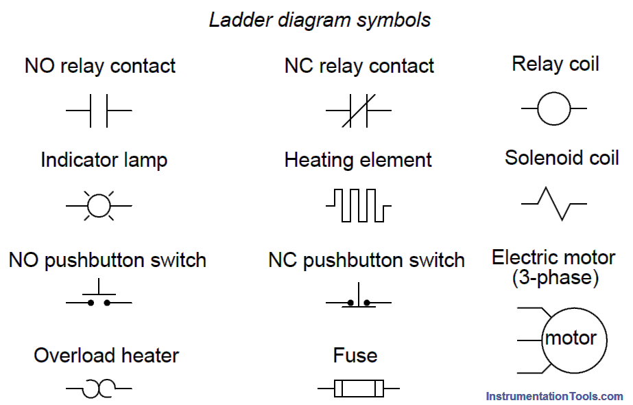
Hydraulic The hydraulic symbol library consists of all the hydraulic symbols and is found under C\Users\Public\Documents\Autodesk\Acade {version}\Libs\hyd_iso125 Float switch HE, HTR Heat exchanger, heaters P&ID. The ladder logic symbols that are used in ladder logic programming have been derived from traditional relay logic control circuits If you have a basic knowledge of electric circuits then getting started in ladder logic programming should be a breeze. Be aware that such symbols as "NO" are not included in the contact point symbols, but are shown just for purposes of illustration Other Basic Switches FAQ What is a Basic Switch?.
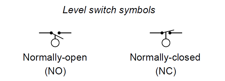
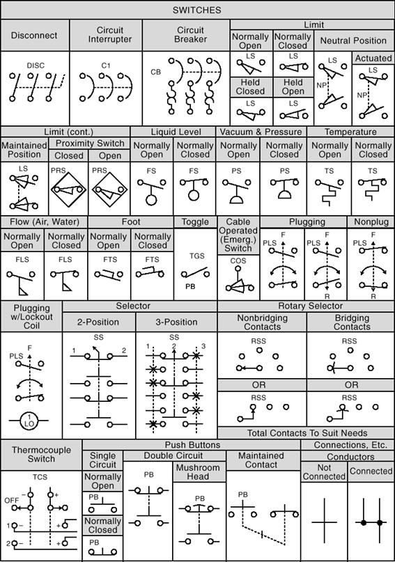
What causes insulation to deteriorate and what can be done about it?. How New Float Switches Work Float switches of the 21st century have come much further in the amount of operations your float switch can perform For example, Water Level Controls is a float switch manufacturer that is revolutionizing the way float switches are used for water level sensing Water Level Control’s NEW Float switches work by using probes (instead of floats) to detect or (sense. Switch Symbols Switch symbols are employed to represent many common control sensing devices There are four basic symbols normally open (NO), normally closed (NC), normally open held closed (NOHC), and normally closed held open (NCHO) To understand how these switches are drawn, it is necessary to begin with how normally open and normally closed switches.
Float level switch Principle Some level switches use a float to sense the level of a liquid surface, actuating an electrical switch by the motion of the float The electrical schematic symbol for a level switch is actually based on this type of mechanism, with a round “ball” float drawn as the actuating element An example of this technology is a level switch manufactured by Magnetrol, with two such switches shown in the following photograph of a steam boiler. And Class II, Divisions 1 and 2, Groups E, F, and G Float Switches for Food and Beverage. Hydraulic The hydraulic symbol library consists of all the hydraulic symbols and is found under C\Users\Public\Documents\Autodesk\Acade {version}\Libs\hyd_iso125 Float switch HE, HTR Heat exchanger, heaters P&ID.
Some level switches use a float to sense the level of a liquid surface, actuating an electrical switch by the motion of the float The electrical schematic symbol for a level switch is actually based on this type of mechanism, with a round “ball” float drawn as the actuating element An example of this technology is a level switch manufactured by Magnetrol, with two such switches shown in the following photograph of a steam boiler These switches sense water level in the steam drum of. Most of the switch symbols can be changed in their appearance, style, and color to meet the requirements The switch symbols below include SPST, SPDT, DPST, DPDT, make contact, break contact, twoway contact, 2 position switch, 3 position switch, 4 position switch, limit switch, inertia switch, mercury switch, and also delay switch such as time delay switch, time delay break, flow actuate. Magnetrol float level controls use a simple float and magnetic coupling action As the float rises or falls with liquid level, it moves a magnetic sleeve into or out of the field of a switch actuating magnet, causing switch operation A nonmagnetic barrier tube effectively isolates the switch mechanisms from the controlled liquid.
The symbols used in piping and Instrumentation diagrams or drawings are many and varied I have dealt with some of these symbols before but here I have given a comprehensive list of the common P&ID symbols of process equipment such as valves, flowmeters, piping line connections, and much more. These switches have no moving parts for a longer life than float switches Dual Float Switches for Sump Pumps If the primary float fails, the backup float kicks in and an alarm sounds to indicate float malfunction. 10 Unit Sequence Switch 11 – Multifunction Device 12 Overspeed Device 13 Synchronousspeed Device 14 Underspeed Device 15 Speed or FrequencyMatching Device Elect operated valve (solenoid valve) 21 Distance Relay 23 Temperature Control Device 24 – Volts per Hertz Relay 25 Synchronizing or SynchronismCheck Device.
Switches Component Circuit Symbol Function of Component Push Switch (pushtomake) A push switch allows current to flow only when the button is pressed This is the switch used to operate a doorbell PushtoBreak Switch This type of push switch is normally closed (on), it is open (off) only when the button is pressed OnOff Switch (SPST). Septic Tank Float Switch Wiring Diagram – septic tank 3 float switch wiring diagram, septic tank float switch wiring diagram, Every electrical arrangement is made up of various diverse components Each part ought to be set and connected with different parts in particular manner If not, the arrangement will not work as it ought to be.
Diagram Reading Plc Wiring Diagram Symbols Full Version Hd Quality Diagram Symbols Selfrewiringh Risparmiatilospreco It

Types Of Switches
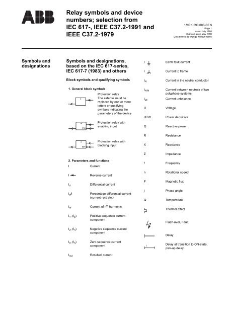
Relay Symbols And Device Numbers Ape Distribuidor Abb
Normally Open And Normally Closed Switch Contacts Electrical Switches
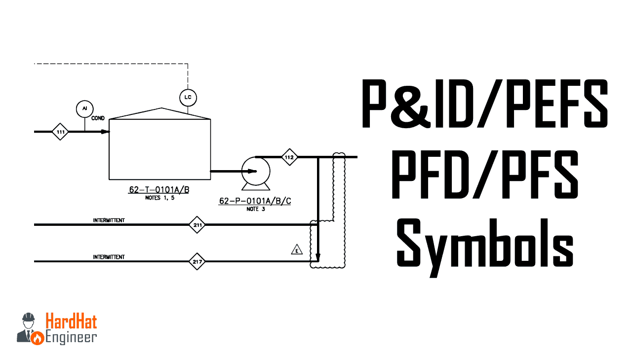
P Id And Pfd Drawing Symbols And Legend List Pfs Pefs
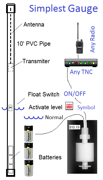
Aprs Flood Gauges
Functions Of Motor Control Sensing Devices Electric Equipment
Solved 26 Chapter 2 Symbols And Schematic Diagrams Review Chegg Com

Float Switch Wikipedia

Jic Standard Symbols For Electrical Ladder Diagrams Womack Machine Supply Company
Marine Man Es Com Applications Projectguides 4stroke Content I 1 Pdf

Float Switches Control Pilot Devices
Float Level Switch Principle Operation Instrumentationtools

Float Level Switches Magnetrol

Bosch Rexroth Float Switch With Two Switching Contacts And One Temperature Contact Type Abzms 35 Hyquip

Level Switches Discrete Process Measurement Automation Textbook
Reading Fluids Circuit Diagrams Hydraulic Pneumatic Symbols

Diagram 3 Wire Float Switch Diagram Full Version Hd Quality Switch Diagram Diagramdubinr Rome Hotels It
Float Switches Rhopoint

Symbols Pdf
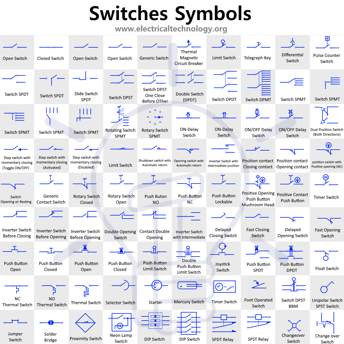
Switch And Push Button Symbols Electrical And Electronic Symbols
Www Eaton Com Content Dam Eaton Products Electrical Circuit Protection Medium Voltage Vacuum Circuit Breakers Comparison Nema Iec Schematic Diagrams Mzen Pdf
1
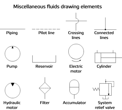
Reading Fluids Circuit Diagrams Hydraulic Pneumatic Symbols
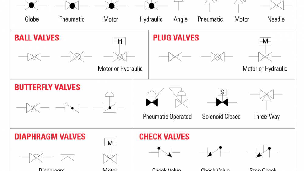
The Most Common Control Valve Symbols On A P Id Kimray

Discount On Understanding Motor Controls Test Bank 17 By Quickmail710 Issuu

Float Switch Installation Wiring Control Diagrams Apg

Electrical Symbols For Other Pilot Devices
Diagram Electrical Ladder Diagrams Float Switches Full Version Hd Quality Float Switches Diagramthornd Macchineassemblaggio It
Types Of Switches
Chp Spare Parts Online Float Switch Original Onergys De
Psi Explained Piping And Instrument Diagrams P Ids

Working Principle Of Float Type Level Switch

Float Switch How It Works Electrical Blog
How To Read A Schematic Understanding Of Graphical Symbols Used In Fluid Power Drawings Air Hydraulic Equipment Inc
Float Switch
P Id And Pfd Drawing Symbols And Legend List Pfs Pefs
Circuit Diagram Electric Electronic Float Switch Level Switch Switch Icon Download On Iconfinder
Q Tbn And9gcsp2uiq 7otklau0 Q9hyc6np4ncptrjhmap5lhatu 6f Usqp Cau
Normally Open Switch Wiring Diagram Symbols 1967 Mgb Tachometer Wiring Begeboy Wiring Diagram Source

Floor Plan Light Switch Symbol New Light Switch Symbol Floor Plan Thebrontesco Cabtivist
Graphical Symbol For Normally Open Held Closed Limit Switch Codes And Standards General Discussion Eng Tips
Q Tbn And9gcswdwlbgril3uijxowspgit4oxfde4t86j0vftqgs5cetmn4gg6 Usqp Cau
Introduction

Directional Control Valves Symbols Hydraulic Valve
P Id Symbols Complete List Pdf Projectmaterials
Big Switch Networks Inc Trademarks Logo Codenames
Introduction

Understanding Motor Controls 3rd Edition Herman Test Bank By Craig Camacho Issuu

Julabo Float Switch Home Fisher Scientific
Hydraulic Symbology 301 Electrical And Electronic Symbols

Water Tank Float Switch Symbol Page 1 Line 17qq Com

Diagram A C Float Switch Wiring Diagram Free Picture Full Version Hd Quality Free Picture Rkwiring Italiadogshow It
Gline Pro Index Php Route Product Product Download Product Id 257 Download Id 1
Ladder Diagram Symbols Flashcard Exercise Get Started Ppt Download
Types Of Switches
Electric Symbols For Hvac Youtube
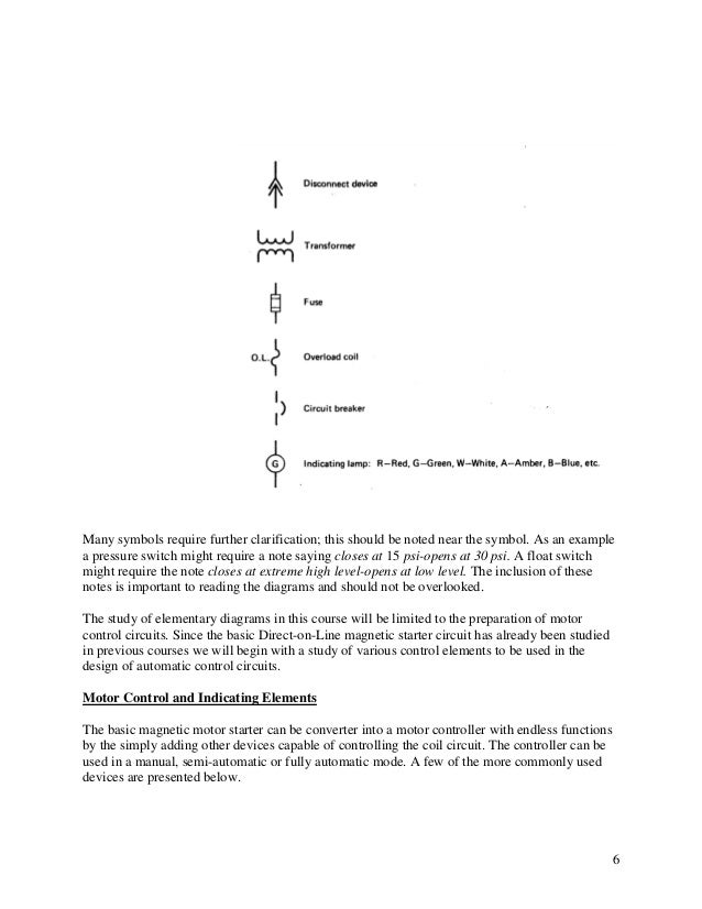
3

Jic Standard Symbols For Electrical Ladder Diagrams Womack Machine Supply Company

Float Switches Control Pilot Devices
Motor Control Circuit Symbols Electric Equipment

Latching Push Button Switch Push Button Switch Push Button Supplier Alan Butcher Components
Www Pnws Awwa Org Uploads Pdfs Conferences 16 Technical sessions Friday P Id Pdf

Chapter 4 Iso Symbols And Glossary Part 3 Hydraulics Pneumatics

Common Process Switches And Their Symbols In P Ids Learning Instrumentation And Control Engineering
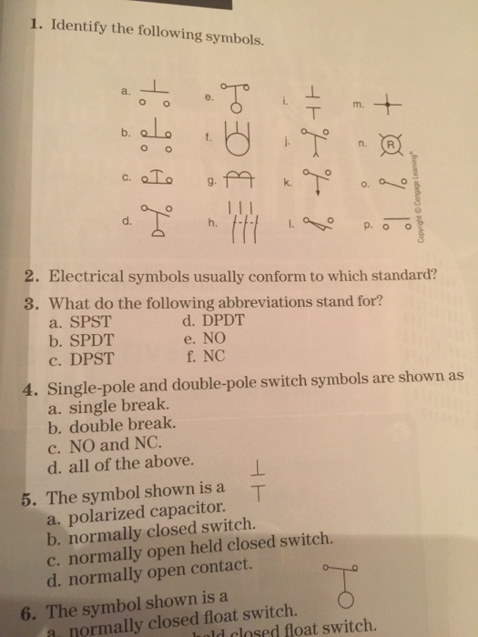
Solved 1 Identify The Following Symbols E B D H 2 Chegg Com

Float Switch Wikipedia
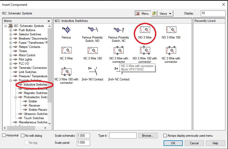
Solved Symbols Prox Switch Three Wire Autodesk Community Autocad Electrical

Float Switch Installation Wiring Control Diagrams Apg

Cover Pump Float Switch Ul Zanussi
Relays In Ladder Logic Tutorials Instrumentation Tools

The Difference Between Normally Open And Normally Closed Float Switch
Electrical Symbols Ieee Std 315 1975 Quick Reference Only

How To Control Level Of A Tank With Float Switch Electrical Blog
Series 15 Side Mounted Float Level Switches

18 Electrical Wiring Diagram Symbols List For You Bacamajalah Electrical Wiring Diagram Electrical Symbols Symbols

Electrical Symbols For Other Pilot Devices

Diagram Electrical Ladder Diagrams Float Switches Full Version Hd Quality Float Switches Diagramthornd Macchineassemblaggio It
Omcq 9650 Sts And 9750 Sts Brazilian Combines Block File Ouo6075 0002c8b 19 09may03 Htm
Hydraulic Symbols Piping And Tubing Symbols Normal Working Line Flexible Working Line Pilot Line Drain Line Enclosure Outline Direction Of Flow Ppt Download

Reed Switch Wikipedia

Water Sensor Switch Wiring Diagram Electrical Wiring Method Schematic Symbols Volvos80 Tukune Jeanjaures37 Fr

Autocad Electrical User S Guide Overview Of Symbol Naming Conventions

Electrical Ladder Diagrams Float Switches Horn Wiring Diagram 91 Mr2 Source Auto3 Tukune Jeanjaures37 Fr

Industrial Motor Control Float Switches
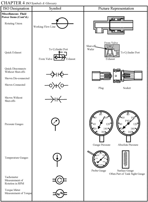
Chapter 4 Iso Symbols And Glossary Part 3 Hydraulics Pneumatics

Light Switch Symbol Lighting And Switch Layout How To Use House Electrical Cabtivist
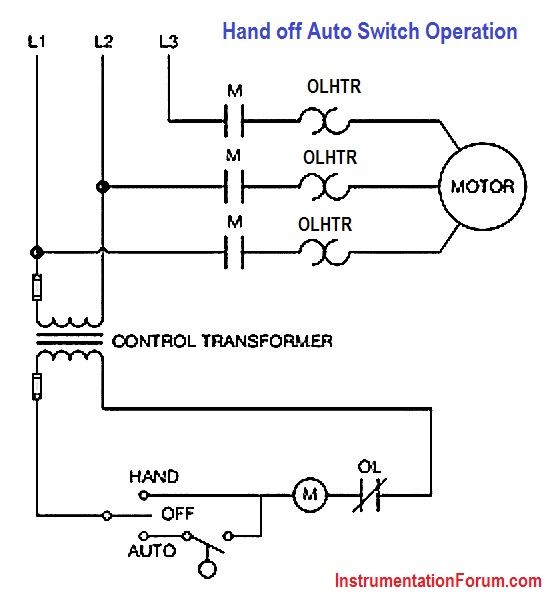
Hand Off Auto Switch Operation Electrical Engineering Instrumentation Forum

Float Switch Symbol Page 1 Line 17qq Com

Industrial Motor Control Symbols And Schematic Diagrams

Float Switch Installation Wiring Control Diagrams Apg
P Id Symbols Complete List Pdf Projectmaterials

Float Switches Control Pilot Devices
Testbankuniv Eu Sample Understanding Motor Controls 3rd Edition Herman Test Bank Pdf
Electrical Symbols Ieee Std 315 1975 Quick Reference Only

Magnetic Waterproof Float Switch Buy Magnetic Waterproof Float Switch Waterproof Switch 12v Micro Float Switch Product On Alibaba Com
Symbol Of Switches Push Buttons Circuit Switches
The Symbol Shown Is A A Normally Closed Float Switch B Normally Open Held Closed Float Switch C Normally Open Float Switch D Normally Closed Held Open Float Switch Bartleby


